| Power System Frequency Monitor |
This is the home of my Power System Frequency Monitor (PSFM) project.
You can view current data from a monitor at my house:
Eastern Interconnect frequency disturbances for the current month
Beginning September 20th 2009, the readings are from the new 1.2 hardware design.
The PSFM is a hobby project I started in early 2006. I work at a power company and part of what I do involves fault recording and disturbance triggering. So this project is related to what I do for a living. It measures the frequency of the power grid via a wall socket. It also triggers for grid disturbances. Typical causes of disturbances are sudden load shifts that cause the interconnect's generators to change speed slightly. A sudden loss of a generator will cause all the other generators on the grid to slow down slightly as they work a bit harder to pick up the slack. Conversely, a sudden loss of load will cause generators to speed up slightly.
I started this project back in the Spring of 2006. A colleague and I were interested in monitoring the frequency of the grid at home. Devices that do that are built for the utility industry and cost thousands of dollars. They also have other funtions we weren't interested in. So I started investigating ways to build a device that only measures frequency and does that from the wall socket in the house.
I ended up building a device using an op-amp to turn the sine wave from the wall into a square wave and I used a Basic Stamp 2 micro-controller to measure the pulse width of the square wave. It worked amazingly well. It wasn't perfect but it did the job and the total cost was around $130 including the enclosure.
The next step was to write software to collect the data and also to trigger for disturbances. I originally wrote the software in Visual Basic 2005 Express, since that was the first environment where I got the serial port code working. Before I got too far, I rewrote the entire program in Delphi, mostly because it was easier, also it's faster and I like the idea of an executable with no dependencies. It now has several triggers:
- Over and under (with time delay)
- Delta frequency disturbance trigger
- Rate of change, based on the operation of the Virginia Tech FNET system's trigger.
The hardware hase been through three revisions. Initially it was just an op-amp configured as a Scmitt trigger. I later changed to a dedicated 7414 (74HC14) Schmitt trigger chip. I changed because that had a much faster published rise time than I was getting with the op-amp. Realistically I didn't notice much difference in the operation.
The next big thing was the addition of a "divide by n" counter: I used a 74HC4059. The reason for that is because of the way the Basic Stamp measures pulses. It can only measure one high or one low pulse. In order to get the resolution I wanted, I needed to measure at least 6 cycles. In the stamp that requires twelve measurements, high and low for each cycle. However, another limitation of the stamp is that it is not ready to measure the low time immediately after measuring the high time. The end result is that it takes 18 cycles to measure six. Also, those 12 measurements have some inaccuracy built in because of the rise time of the square wave.
That's when I got the idea to divide the square wave external to the stamp. Once I did that, I was able to measure 6 cycles with one measurement instead of 12, and I was ready to make a new measurement after waiting one cycle. So I got a new reading every 7 cycles that was the measurement of 6 cycles. Immediately my sample rate went from 3.3 samples/second to 8.5 samples/second with no loss of accuracy and a very noticeable reduction of jitter in the measurement! Using jumpers, the divide by n counter is programmable.
I also started thinking it would be nice to measure for a longer period in order to improve the resolution, but the Basic Stamp can only count to 65536, which works out to just a bit over 7 cycles. I did some more searching on the internet and dicovered a pin compatible device call the ARMExpress Lite. It fits in the same socket as the stamp and can be programmed in either Basic or C. It has several advantages over the Basic Stamp 2:
- Its resolution is one microsecond, vs two microseconds for the BS2
- It can count 16 bits higher than the BS2
- It has analog inputs!
- More program memory
- More RAM (variable memory)
- it runs much faster (60 Mhz vs 20)
- It costs exactly the same.
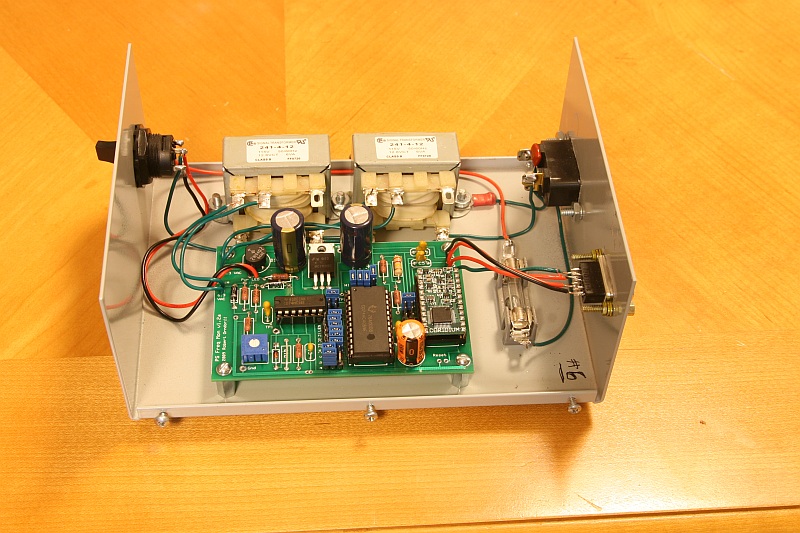
Here is a picture of the current version. The jumpers program the divide by n counter (74HC4059). Currently I am using two transformers, one for power and one for sensing. The transformers are oversized for this project, but I think the larger transformer is good for sensing - it produces a nice clean sine wave, but not needed for power. I think I can eliminate one of the transformers in the new design. The small chip is the 74HC14 Schmitt trigger, the big chip in the middle is the divide by n counter and the chip on the right is the ARMExpress or Basic Stamp 2.
I made the circuit boards using ExpressPCB, excellent quality and service and free software! The rest of the parts came from Digikey and Mouser.
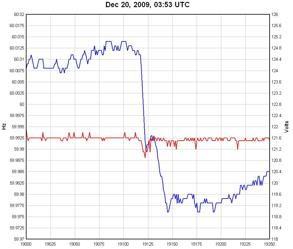
Here's a graph of an event that occurred December 20, 2009 at 03:53 UTC. Note the slight voltage drop. This event appears to be the loss of a generating unit in Millstone, CT.
The voltage and frequency are raw data captured by one of my recorders in my house in Richmond, VA.
I used DPlot to create the graph. The time scale is in samples. In this case it is 6 samples/second, and 19125 samples is about 53 minutes. (A new recording is generated evry hour).
Here's the trigger data. If my triggers are set correctly, the delta f value should be a good approximation of the frequency change. Each trigger does independent calculation of slope and delta f. "Pickup" is the time the trigger asserts and "Dropout" is the time when the trigger quantities drop below the setting threshold.
| Date | Pickup | Dropout | Delta F | Slope (Hz/sec) | Trigger |
| 12/20/09 | 03:53:11 | 03:53:17 | -0.034 | -0.0068 | VT ROC |
| 12/20/09 | 03:53:10 | 03:53:20 | -0.034 | -0.0066 | Delta - |
Thanks to Jim Ingleson, The Virginia Tech FNET Project, and Arnold Stadlin ( PHzMonitor). They have all provided help and feedback in making this thing work and improving it.
Downloads for PSFM
Updated December 21, 2009 - Robert Orndorff
Robert's web site