
Monitoring TTL IRIG with an Arduino
December 21, 2016
This document describes how to monitor a TTL IRIG signal using an Arduino controller. Some familiarity with the Arduino and electronics is needed, as well as some computer expertise. Make sure you know that you are connecting to the proper output of your clock. If you don’t know then you can use an oscilloscope to determine which output contains the IRIG signal.
This project involves electrical and electronic wiring and connections. If you are not comfortable with this type of work, then this is not the project for you. Use these instructions at your own risk. The author assumes no responsibility for anything that occurs while following these instructions. That being said, we have used this setup many times with no problems at all.
Supplies needed:
- Arduino Uno R3 (have also tested on a Mega) Available at Amazon, arduino.cc, and many other retailers.
- USB cable, type A to type B. This is used to connect the Arduino to your PC and also to provide power to the Arduino.
- A PC running Windows
- decoder software, Windows IRIG Decoder with source code, Windows IRIG Decoder, no source code:
- A terminal program (PuTTY, Teraterm, etc.)
- Arduino IDE
- A way to connect the IRIG signal to the Arduino. We used a BNC to clip jumper adapter and hook up wire into the pins on the Arduino.
- Arduino program source code (IRIG_Decoder_Arduino_source).
Update – 2018-01-28. I have a new program that automatically connects to the Arduino, decodes the data and logs both raw and decoded data simultaneously. It’s still a work in progress, but perfectly functional. Click the link below to download.
Version 2 of the IRIG decoder program
To get started:
- Load the IRIG_Decoder.ino code onto the Arduino using the Arduino IDE.
- Connect an IRIG (TTL, 5 volt square wave) to the Arduino with the signal on digital input 8 and ground on the AREF pin. See Figure 1. The connection is direct to the clock output and no buffering or isolation is necessary.
- Open your terminal program and set it to use the COM port associated with the Arduino. 9600 baud, 8,N,1
- If everything is working (and it should be), you should see a steady stream of data coming across your terminal screen. It should look like the data shown below.
M
 10010000M
 110000000M
 000001000M
 000000010M
 110000000M
 011001000M
 000011010M
 000000100M
 101110101M
 011000100M
 M
 00000100M
Once you are seeing the data come through, turn on the logging or text capture feature of your terminal program and capture the raw IRIG data to a file.
Once you have the data desired, you then open the capture file with the “IRIG Decoder.exe” Windows program. With this program, you can browse through the data frames, or just convert the whole file to .csv format. The .csv file will open in Excel, where you can examine the captured data.
Note: The “IRIG Decoder.exe” program is a bit slow, and is not polished. It is entirely functional, though. At this point it is simply a utility program. Future versions of this program will do away with the need to capture the data using a third party program, and will decode in real time. For now, though, this is what we have. You are welcome to improve on this program or write your own. I ask that you let me know about any improvements made so I can distribute them as needed. This version is written in VB.net.
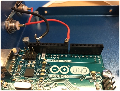
IRIG connections to Arduino board
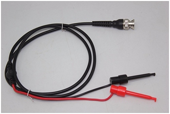
BNC to clip leads
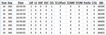
Output of the Windows decoder program viewed in Excel
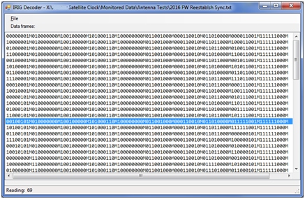
Screenshot of the main window of the decoder program
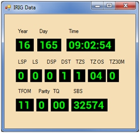
Display of decoded data
Technical description
The IRIG signal contains BCD (binary coded decimal) representations of the time of day, year, and other information. A “One” is represented by a square wave pulse that is 5 milliseconds in length. A “zero” is represented by a pulse that is 2 milliseconds in length. There is also a Position Identifier, or marker bit that is represented by a pulse that is 8 milliseconds wide. The Arduino program decodes the IRIG pulses into a 1, 0, or M and sends this data to the serial port. Two marker bits in a row indicate the start of a new data frame. When the Arduino encounters a marker bit, it writes an “M” followed by a new line character. This series of ones, zeros, and marker bits is captured to a text file. This text file is then decoded by the Windows decoder program.
Monitoring events
We have used this setup to monitor many of the “edge” events that occur, such as leap seconds, year rollover, and the changes to and from Standard and Daylight time. If, for example, you are monitoring for a leap second event, you should start monitoring well in advance of the change. We typically start logging data about 20-30 minutes prior, but the important changes in the IRIG data stream happen no more than one minute prior to the actual time event. When the event occurs during a weekend or holiday, we have started monitoring several days in advance. This can result in a very large data file (we’ve dealt with 60-80MB files that cover a week) that takes a while to process, but it works just fine.
Be aware of the time that these events occur. Leap seconds happen at UTC midnight, which occurs several hours before local midnight in the US time zones.
Technical details about the various flavors of the IRIG time code can be found here:
https://www.meinbergglobal.com/english/info/irig.htm
We have found an enclosure that is modestly priced that works well to house the Arduino and comes with two pre-installed BNC connectors.
http://www.iaasr.com/product/custom-arduino-enclosure/
PuTTY
http://www.chiark.greenend.org.uk/~sgtatham/putty/download.html
TeraTerm
http://ttssh2.osdn.jp/index.html.en
Arduino IDE
https://www.arduino.cc/en/Main/Software
Arduino UNO R3
https://www.amazon.com/Arduino-Uno-R3-Microcontroller-A000066/dp/B008GRTSV6
USB cable
https://www.amazon.com/AmazonBasics-USB-2-0-Cable-Male/dp/B00NH11KIK/
//Pin 8 is used for the TTL IRIG Input
int pin=8;

void setup() {
  //Initialize serial and wait for port to open:
  Serial.begin(9600);
  while (!Serial) {
    ; // wait for serial port to connect. Needed for Leonardo only
  }

  pinMode(pin,INPUT);
  // prints title with ending line break
  Serial.println("IRIG data capture");
}

void loop() {
  // put your main code here, to run repeatedly:
  unsigned long duration;

  duration=pulseIn(pin,HIGH,1000000);
  //Serial.println(duration);
  if (duration>1700 && duration<2300)
  {
    //2 ms
    Serial.print("0");
  }

  if (duration>4700 && duration<5300)
  {
    //5 ms
    Serial.print("1");
  }

  if (duration>7700 && duration<8300)
  {
    //8 ms
    Serial.println("M");
  }


  //delay(1000);

}